Why Transformer Rating In kVA, Not in KW?

Why Transformer Rating In kVA, Not in KW?

In Simple words, 
There are two type of losses in a transformer:
1. Copper Losses
2. Iron Losses or Core Losses or  Insulation Losses
Copper losses ( I²R)depends on Current which passing through transformer winding while Iron Losses or Core Losses or  Insulation Losses depends on Voltage.
That’s why the Transformer Rating may be expressed in kVA,Not in kW.


Different types of transformer

Different types of transformer

Types of Transformers:

There are two basic Types of Transformers
  1. Single Phase Transformer
  2. Three Phase Transformer
Below are the more types of transformer derived via different functions and operation etc.

Types of Transformers w.r.t Cores:

  • Core Type Transformer
  • Shell Type Transformer
  • Berry Type Transformer

Types of Transformer w.r.t uses:

  • Large Power Transformer
  • Distribution Transformer
  • Small Power Transformer
  • Sign Lighting Transformer
  • Control & Signalling Transformer
  • Gaseous Discharge Lamp Transformer
  • Bell Ringing Transformer
  • Instrument Transformer
  • Constant Current Transformer
  • Series Transformer for Street Lighting

Types of Transformer w.r.t Cooling:

  • Self Air Cooled or Dry Type Transformer
  • Air Blast-Cooled Dry Type
  • Oil Immersed, Self Cooled (OISC) or ONAN (Oil natural, Air natural)
  • Oil Immersed, Combination of Self Cooled and Air blast (ONAN)
  • Oil Immersed, Water Cooled (OW)
  • Oil Immersed, Forced Oil Cooled
  • Oil Immersed, Combination of Self Cooled and Water Cooled (ONAN+OW)
  • Oil Forced, Air forced Cooled (OFAC)
  • Forced Oil, Water Cooled (FOWC)
  • Forced Oil, Self Cooled (OFAN)

Types of  Instrument Transformer:

  • Current Transformer
  • Potential Transformer
  • Constant Current Transformer
  • Rotating Core Transformer or Induction regulator
  • Auto Transformer


Different Parts of Transformer

Different Parts of Transformer

1.
Oil filter valve
17.
Oil drain valve
2.
Conservator
18.
Jacking boss
3.
Buchholz relay
19.
Stopper
4.
Oil filter valve
20.
Foundation bolt
5.
Pressure-relief vent
21.
Grounding terminal
6.
High-voltage bushing
22.
Skid base
7.
Low-voltage bushing
23.
Coil
8.
Suspension lug
24.
Coil pressure plate
9.
B C T Terminal
25.
Core
10.
Tank
26.
Terminal box for protective devices
11.
De-energized tap changer
27.
Rating plate
12.
Tap changer handle
28.
Dial thermometer
13.
Fastener for core and coil
29.
Radiator
14.
Lifting hook for core and coil
30.
Manhole
15.
End frame
31.
Lifting hook
16.
Coil pressure bolt
32.
Dial type oil level gauge.

Introduction to Electrical Transformer

Introduction to Electrical Transformer

What is a Transformer?

In Very Simple words.
Transformer is a device which:
  1. Transfer Electrical power from one electrical circuit to another Electrical circuit.
  2. It’s working without changing the frequency.
  3. Work through on electric induction.
  4. When, both circuits take effect of mutual induction.
  5. Can’t step up or step down the level of DC voltage or DC Current.
  6. Can step up or step down the level of AC voltage or AC Current.

  • Without transformers the electrical energy generated at generating stations won’t probably be sufficient enough to power up a city. Just imagine that there are no transformers.How many power plants do you think have to be set up in order to power up a city? It’s not easy to set up a power plant. It is expensive.
  • Numerous power plant have to be set up in order to have sufficient power. Transformers help by amplifying the Transformer output (stepping up or down the level of voltage or current).
  • When the number of turns of the secondary coil is greater than that of primary coil, such a transformer is known as step up transformer.
  • Likewise when the number of turns of coil of primary coil is greater than that of secondary transformer, such a transformer is known as step down transformer.


Why we are use 11KV / 22KV / 33KV / 66KV / 110KV / 230KV / 440KV this type of ratio?

Why we are use 11KV / 22KV / 33KV / 66KV / 110KV / 230KV / 440KV this type of ratio. Why can’t we use other voltage ratio like 54KV / 99KV etc?

When an alternator generates voltage, we always use a multiple of 1.11 because for a pure sine wave the FORM FACTOR is the  ratio of rms value of voltage or current with the avg. value of voltage or current and for pure sine wave rms value of current is Imax/root '2' and avg. value is 2Imax/pie and which comes out to be 1.1;


We can't have a combination of other then a multiple of 1.11*.
So we can see all the voltages are made inevitably multiple of this value (1.1, which is the form factor of ac wave).

Also it provides us the best economic construction of step up and step down transformers.


* In the case of a Square Wave ie. a digital wave, the RMS and the average value are equal; therefore, the form factor is 1.


Different type of motors...

Different type of motors.....

Squirrel Cage Motor


Electric Motor

An Electric motor is a machine which converts electric energy into mechanical energy. Its action is based on the principle that when a current-carrying conductor is placed in a magnetic field, it experiences a mechanical force whose direction is given by Fleming’s Left-hand Rule and whose magnitude is given by F = BIl Newton.

Types of AC Motors

Classification Based On Principle of Operation:
(a) Synchronous Motors.
1. Plain
2. Super

(b) Asynchronous Motors.
1. Induction Motors:
(a) Squirrel Cage
(b) Slip-Ring (external resistance).
2. Commutator Motors:
(a) Series
(b) Compensated
(c) Shunt
(d) Repulsion
(e) Repulsion-start induction
(f) Repulsion induction
Classification Based On Type of Current:
1. Single Phase
2. Three Phase
Classification Based On Speed of Operation:
1. Constant Speed.
2. Variable Speed.
3. Adjustable Speed.
Classification Based On Structural Features:
1. Open
2. Enclosed
3. Semi-enclosed
4. Ventilated
5. Pipe-ventilated
6. Riveted frame-eye etc. 

Types of DC Motor

Most common DC motor types are-
1. Permanent-magnet motors
2. Brushed DC Motor
a.       DC shunt-wound motor
b.      DC series-wound motor
c.       DC compound motor
                                                              i.      Cumulative compound
                                                            ii.      Differentially compounded
d.      Permanent magnet DC motor
e.       Separately excited

3. Brushless DC Motor
4. Coreless or ironless DC motors
5. Printed armature or pancake DC motors
6. Universal motors


How to choose transformer rating?

 How to choose transformer rating?


When an installation is to be supplied directly from a MV/LV transformer and the maximum apparent-power loading of the installation has been determined, a suitable rating for the transformer can be decided, taking into account the following considerations:


  • The possibility of improving the power factor of the installation
  • Anticipated extensions to the installation
  • Installation constraints (e.g. temperature)
  • Standard transformer ratings.

3-phase transformer

The nominal full-load current In on the LV side of a 3-phase transformer is given by:

Formula - transformer rating

where:
  • Pa = kVA rating of the transformer
  • U = phase-to-phase voltage at no-load in volts (237 V or 410 V)
  • In is in amperes

Single-phase transformer

For a single-phase transformer:

Formula2 - transformer rating

where
  • V = voltage between LV terminals at no-load (in volts)
Simplified equation for 400 V (3-phase load)
  • In = kVA x 1.4
The IEC standard for power transformers is IEC 60076.

Degradation of Insulation in Switchgear (What’s Really Happening)

Partial Discharge

Partial Discharge (PD)

Electrical insulation is subjected to electrical and mechanical stress, elevated temperature and temperature variations, and environmental conditions especially for outdoor applications. In addition to normal operating conditions, there are a host of other factors that may trigger accelerated aging or deterioration of insulation.


Switching and lightning surges can start ionization in an already stressed area. Mechanical strikes during breaker operation can cause micro cracks and voids. Excessive moisture or chemical contamination of the surface can cause tracking. Any defects in design and manufacturing are also worth mentioning.
Partial Descharge


PD is a localized electrical discharge that does not completely bridge the electrodes. PD is a leading indicator of an insulation problem. Quickly accelerating PD activity can result in a complete insulation failure.

PD mechanism can be different depending on how and where the sparking occurs:
  • Voids and cavities are filled with air in poorly cast current transformers, voltage transformers and epoxy spacers. Since air has lower permittivity than insulation material, an enhanced electric field forces the voids to flash-over, causing PD. Energy dissipated during repetitive PD will carbonize and weaken the insulation.
  • Contaminants or moisture on the insulation induce the electrical tracking or surface PD. Continuous tracking will grow into a complete surface flash-over.
  • Corona discharge from sharp edge of a HV conductor is another type of PD. It produces ozone that aggressively attacks insulation and also facilitates flashover during periods of overvoltage.
Features of partial discharge activity, such as intensity, maximum magnitude, pulse rate, long-term trend, are important indications of the insulation’s condition.

Healthy switchgear has very little or no PD activity. If PD activity is significant, it will eventually deteriorate insulation to a complete failure. Higher voltages produce higher intensity partial discharges, thus PD detection in gear with higher voltages (13.8 kV and up) is more critical.

Possible locations of partial discharge in switchgear:
  1. Main bus insulation
  2. Circuit breaker insulation
  3. Current transformers
  4. Voltage transformers
  5. Cable terminations
  6. Support insulators
  7. Non-shielded cables in contact with other phases or ground


Electrical Switchgear Protection

Definition of Switchgear

A switchgear or electrical switchgear is a generic term which includes all the switching devices associated with mainly power system protection. It also includes all devices associated with control, metering and regulating of electrical power system. Assembly of such devices in a logical manner forms a switchgear. This is very basic definition of switchgear.

Switchgear and Protection

Switchgear
 We all familiar with low voltage switches and re-wirable fuses in our home. The switch is used to manually open and close the electrical circuit in our home and electrical fuse is used to protect our household electrical circuit from over  current  and short circuit faults. In same way every electrical circuit including high voltage electrical power system needs switching and protective devices. But in high voltage and extra high voltage system, these switching and protective scheme becomes complicated one for high fault  current  interruption in safe and secure way. In addition to that from commercial point of view every electrical power system needs measuring, control and regulating arrangement. Collectively the whole system is called switchgear and protection of power system. The electrical switchgear have been developing in various forms.

Switchgear protection plays a vital role in modern power system network, right from generation through transmission to distribution end. The  current  interruption device or switching device is called circuit breaker in switchgear protection system. The circuit breaker can be operated manually as when required and it is also operated during over  current  and short circuit or any other faults in the system by sensing the abnormality of system. The circuit breaker senses the faulty condition of system through protection relay and this relay is again actuated by faulty signal normally comes from current transformer or voltage transformer.

A switchgear has to perform the function of carrying, making and breaking the normal load current  like a switch and it has to perform the function of clearing the fault  in addition to that it also has provision of metering and regulating the various parameters of electrical power system. Thus the switchgear includes circuit breaker, current transformer, voltage transformer, protection relay, measuring instrument, electrical switch,electrical fuse, miniature circuit breaker, lightening arrestor or surge arrestor, electrical isolator and other associated equipment.
Switchgear Panels
 
 
Electric switchgear is necessary at every switching point in the electrical power system. There are various voltage levels and hence various fault levels between the generating stations and load centers. Therefore various types of switchgear assembly are required depending upon different voltage levels of the system.
 
Besides the power system network, electrical switchgear is  also required in industrial works, industrial projects, domestic and commercial buildings.


PSIM Software

PSIM Software

PSIM Software

PSIM is one of the fastest simulators for power electronics simulation. It achieves fast simulation while retaining excellent simulation accuracy. This makes it particularly efficient in simulating converter systems of any size, and performing multiple-cycle simulation.

PSIM is the engine of the simulation environment. PSIM uses a strong algorithm dedicated to electrical circuits (piecewise method, generic models and a fixed time-step). The fast simulation allows repetitive simulation runs and significantly shortens the design cycle.

PSIM can simulate control circuit in various forms: in analog circuit, s-domain transfer function block diagram, z-domain transfer function block diagram, custom C code, or in Matlab/Simulink®. PSIM’s control library provides a comprehensive list of components and function blocks, and makes it possible to build virtually any control scheme quickly and conveniently.

Download:Download Now

The Switchboard Design Requirements

Switchboard Panel

The Switchboard Design Requirements

Design Rules

The following rules of design have to be implement in the aim to facilitate the assembly and especially the maintenance of the installation.

The switchboard must be designed the way to have a clearly visible separation between the 3 following zones:
  • One dedicated for the devices installation
  • One dedicated for the bus bars mounting
  • and one dedicated for the out-goers cables connections 

Switchboard Areas

The goal of that architecture is to separate the switchboard in different areas in function of each professional user.
  • Devices zone => panel builder and exploiter
  • Bus bars zone => panel builder
  • Cable connection zone => installer and maintenance

In order to facilitate the access within the switchboard for the maintenance, its covering panels must be dis-mountable on all surfaces for any IP degree.

All the devices must be installed onto dedicated mounting plate designed for one or several switchgear of the same type. The objective of that point is to regroup the protection equipment of the same nature each others and distinguish inside the switchboard the function of each device or group of devices.

Theses mounting plates will have an independent fixing system affording them to be transformed and moved anywhere in the switchboard and especially to make it easier the installation evolution.
To insure the maximum protection of people around the electrical installation, front plates must be installed in front of all control and protection equipment in order to avoid a direct access without a tool to the devices and consequently to the active parts.

For safety reasons and especially when the door will be opened during the switchboard working, all bus bars have to be covered by barriers onto the whole perimeter of the bus bars zone.

Maintenance Of Meduim Voltage Circuit Breakers

Medium Voltage Circuit Breaker

Maintenance Of Medium Voltage Circuit Breakers

Medium-voltage circuit breakers rated between 1 and 72 kV may be assembled into metal-enclosed switchgear line ups for indoor use, or may be individual components installed outdoors in a substation. Air-break circuit breakers replaced oil-filled units for indoor applications, but are now themselves being replaced by vacuum circuit breakers (up to about 35 kV). Medium voltage circuit breakers which operate in the range of 600 to 15,000 volts should be inspected and maintained annually or after every 2,000 operations, whichever comes first.

The above maintenance schedule is recommended by the applicable standards to achieve required performance from the breakers.

Maintenance procedures include the safety practices indicated in the ROMSS (Reclamation Operation & Maintenance Safety Standards) and following points that require special attention.
  • Be sure the circuit breaker and its mechanism are disconnected from all electric power, both high voltage and control voltage, before it is inspected or repaired.
  • Exhaust the pressure from air receiver of any compressed air circuit breaker before it is inspected or re­paired.
  • After the circuit breaker has been disconnected from the electrical power, attach the grounding leads properly before touching any of the circuit breaker parts.
  • Do no lay tools down on the equipment while working on it as they may be forgotten when the equipment is placed back in service.

Maintenance Procedures For:

Medium Voltage Air Circuit Breakers

The following suggestions are for use in conjunction with manufacturer’s instruction books for the maintenance of medium voltage air circuit breakers:
  1. Clean the insulating parts including the bushings.
  2. Check the alignment and condition of movable and stationary contacts and adjust them per the manufacturer’s data.
  3. See that bolts, nuts, washers, cotter pins, and all terminal connections are in place and tight.
  4. Check arc chutes for damage and replace damaged parts.
  5. Clean and lubricate the operating mechanism and adjust it as described in the instruction book. If the operat­ing mechanism cannot be brought into specified tolerances, it will usually indicate excessive wear and the need for a complete overhaul.
  6. Check, after servicing, circuit breaker to verify that contacts move to the fully opened and fully closed positions, that there is an absence of friction or binding, and that electrical operation is functional.


Medium Voltage Oil Circuit Breakers

The following suggestions are for use in conjunction with the manufacturer’s instruction books for the maintenance of medium-voltage oil circuit breakers:
  1. Check the condition, alignment, and adjustment of the contacts.
  2. Thoroughly clean the tank and other parts which have been in con­ tact with the oil.
  3. Test the dielectric strength of the oil and filter or replace the oil if the dielectric strength is less than 22 kV. The oil should be filtered or replaced whenever a visual inspection shows an excessive amount of carbon, even if the dielectric strength is satisfactory.
  4. Check breaker and operating mechanisms for loose hardware and missing or broken cotter pins, retain­ ing rings, etc.
  5. Adjust breaker as indicated in instruction book.
  6. Clean and lubricate operating mechanism.
  7. Before replacing the tank, check to see there is no friction or binding that would hinder the breaker’s operation. Also check the electrical operation. Avoid operating the breaker any more than necessary without oil in the tank as it is designed to operate in oil and mechanical damage can result from excessive operation without it.
  8. When replacing the tank and refilling it with oil, be sure the gaskets are undamaged and all nuts and valves are tightened properly to prevent leak­ age.

Medium Voltage Vacuum Circuit Breakers


Direct inspection of the primary contacts is not possible as they are enclosed in vacuum containers. The operating mechanisms are similar to the breakers discussed earlier and may be maintained in the same manner. The following two maintenance checks are suggested for the primary contacts:
  1. Measuring the change in external shaft position after a period of use can indicate extent of contact erosion. Consult the manufacturer’s instruction book.
  2. Condition of the vacuum can be checked by a hipot test. Consult the manufacturer’s instruction book.


ABB – 145kV Compact indoor substation with Disconnecting CB

ABB – 145kV Compact indoor substation with Disconnecting CB

Turnkey 145 kV S/S project for Borlänge Energi, Sweden, emphasizing the advantages of ABB Disconnecting Circuit Breakers. Small footprint enables indoor air insulated Switchgear solutions, increasing the power substation availability and reliability for the customer.
As a complement to the basic version of our LTB circuit breakers, which are primarily designed for conventional substation solutions, there is a disconnecting circuit breaker configuration with the disconnecting function integrated in the breaking chamber.

The LTB Disconnecting Circuit Breaker (DCB) is based on the LTB standard circuit breaker. The disconnecting function is integrated in the breaking chamber. That means that the circuit breaker fulfills all requirements for a circuit breaker as well as all requirements for a dis-connector. A safe interlocking system, composite insulators and a motor driven grounding switch provide personal safety.

With DCB we have created the capability to design substations without conventional dis-connectors, which improves operational availability.

Basic Refrigeration Cycle

Basic Refrigeration Cycle

Principles of Refrigeration

  • Liquids absorb heat when changed from liquid to gas
  • Gases give off heat when changed from gas to liquid.
For an air conditioning system to operate with economy, the refrigerant must be used repeatedly. For this reason, all air conditioners use the same cycle of compression, condensation, expansion, and evaporation in a closed circuit. The same refrigerant is used to move the heat from one area, to cool this area, and to expel this heat in another area.
  • The refrigerant comes into the compressor as a low-pressure gas, it is compressed and then moves out of the compressor as a high-pressure gas.
  • The gas then flows to the condenser. Here the gas condenses to a liquid, and gives off its heat to the outside air.
  • The liquid then moves to the expansion valve under high pressure. This valve restricts the flow of the fluid, and lowers its pressure as it leaves the expansion valve.
  • The low-pressure liquid then moves to the evaporator, where heat from the inside air is absorbed and changes it from a liquid to a gas.
  • As a hot low-pressure gas, the refrigerant moves to the compressor where the entire cycle is repeated.
Note that the four-part cycle is divided at the center into a high side and a low side This refers to the pressures of the refrigerant in each side of the system.


Block diagram of a typical battery

Block diagram of typical battery

Block diagram of a typical battery


Figure  shows a simplified block diagram of a typical battery pack. It consists of the main battery cell and an equivalent series resistance (ESR). The internal impedance of a battery is dependent on the specific battery’s size, chemical properties, age, temperature and the discharge current. Hence, the voltage measured at the terminals of the battery is the sum of the voltage drop across the ESR and the battery cell voltage. Given the sensitivity of this Li-ion and Li-polymer batteries, battery packs are required to include protection circuitry to prevent runaway events. These safety electronics ensure that the cell is not exposed to over-/under-voltage and/or over-current situations.

Why alternator rated in kVA. Not in kW?

Alternator

Why alternator rated in kVA. Not in kW?

The power √3 VL IL Cos φ delivered by the alternator for the same value of current, depends upon p.f. (Power Factor=Cos φ) of the load. But the alternator conductors are calculated for a definite current and the insulation at magnetic system are designed for a definite voltage independent of p.f. (Cos φ) of the load. For this reason apparent power measured in kVA is regarded as the rated power of the alternator.

Essential or need of starter with motor.

Essential or need of starter with motor.

Motors below 1 Hp is directly connect without starter because their armature resistance is very high and they have ability to afford the high current due to high resistance. So the Armature winding safe from the high starting current.
 
But a large size of motors has a very low armature resistance. if connect  this type of motor direct to Supply (3-phase Supply) then the large current will destroy the armature wading due to low resistance because motor is not running in this time. Why motor is not running in this time when we connect motor to supply? Obviously, because their is no Back E.M.F in the motor. the back E.M.F of the motor is reach at full rate when motor is running at full speed.
 
So this is the answer that why we connect a starter with motor in series.  Starter in series with motor ( I.e. Resistance) is reduce the high starting current and armature takes a low current and motor will be start. But this is not end of our story. After starting the  motor at low current, the starter resistance reduce by turning a starter handle ( not in each case, in other system or case, this can be automatically) so the armature will take high current and motor armature will be rotate at full speed ( in other words, the speed of the motor will be increase).

For more Explanation see the example.

We know that the armature current can be finding by this formula,
Ia = V-Eb/Ra       ,             ( I=V/R, Ohm Law)
        Where,      
Ia =Armature current
V= Supply voltage
Eb= Back E.M.F                                           
Ra = Armature resistance
Suppose
A 5 Hp (3.73killowatt) motor with 440 volts having armature resistance 0.25 ohm resistance.
And the normal full load current is 50 amperes.
if we connect to direct to supply without starter the result will be.
So putting the values in equation
Ia= 440-0/0.25 = 1760 A
ahh! This high current will destroy armature winding because its 35.2 times high with respect to normal full load current.
1760/50 = 35.2


Working principle of Transformer

Transformer

Working principle of Transformer

Transformer works on the principle of mutual induction of two coils or Faraday Law’s Of Electromagnetic induction. When current in the primary coil is changed the flux linked to the secondary coil also changes. Consequently an EMF is induced in the secondary coil due to Faraday law’s of electromagnetic induction.

Explanation

The transformer is based on two principles: first, that an electric current can produce a magnetic field (electromagnetism), and, second that a changing magnetic field within a coil of wire induces a voltage across the ends of the coil (electromagnetic induction). Changing the current in the primary coil changes the magnetic flux that is developed. The changing magnetic flux induces a voltage in the secondary coil.


Why we can’t store AC in Batteries instead of DC?

Wave form of AC & DC

Why we can’t store AC in Batteries instead of DC.or Can we store AC in batteries instead of DC?

We cannot store AC in batteries because AC changes their polarity up to 50 (When frequency = 50 Hz) or 60 (When frequency = 60 Hz) times in a second. Therefore the battery terminals keep changing Positive (+ve) becomes Negative (-Ve) and vice versa, but the battery cannot change their terminals with the same speed so that’s why we can’t store AC in Batteries.

in addition, when we connect a battery with AC Supply, then It will charge during positive half cycle and discharge during negative half cycle, because the Positive (+ve) half cycle cancel the negative (-Ve) half cycle, so the average voltage or current in a complete cycle is Zero. So there is no chance to store AC in the Batteries.

Good to know:  Average Voltage x Average Current Average Power.


Basic Electrical Quantities Formulas With Simple Explanation (in DC Circuits.)


Basic Electrical Quantities Formulas With Simple Explanation (in DC Circuits.)

  1. Voltage
  2. Current
  3. Resistance
  4. Power
Power
Electric power is the rate at which electric energy is transferred by an electric circuit. The SI unit of power is the watt, one joule per second.

Current
An electric current is a flow of electric charge or a flow of electron though an electrical conductor. The SI unit for measuring an electric current is the ampere A, which is the flow of electric charges through a surface at the rate of one coulomb per second.

Voltage
Voltage is the potential difference between two points. The SI unit of Voltage is Volt or joules per coulomb.

Resistance
The electrical resistance of an electrical element is the opposition to the passage of an electric current through that elements. The SI unit of electric resistance is the ohm.

How to Wire a Switch and a Load (a Light Bulb) to an Electrical Supply

How to Wire a Switch and a Load (a Light Bulb) to an

Electrical Supply? 

As can be seen in the diagram the wiring is pretty simple. The Phase is invariably applied to one terminal of the switch, the other terminal moves to one of the connections of the load, and the other point of the load continues to finish at the Neutral of the supply line. Toggling the switch will alternately switch the bulb ON and OFF.

Differences between E.M.F and Voltage (P.d)

Differences between E.M.F and Voltage (P.d)

The following are the difference between E.M.F and P.D.
  • The name E.M.F at first sight implies that it is a force that causes current to flow.But this is not correct because it is not a forced but energy supplied to charge some active device such as battery.

  • E.M.F maintains p.d. while p.d. cause current to flow.

  • When we say that E.M.F of a device (e.g., a cell) is 3V it means that the device supplies energy of 3 joules to each coulomb of charge. When we say that a p.d. between point A and B of a circuit (suppose point A is at higher potential) is 3V, it means that each coulomb of charge will give up an energy of 3 joule in moving from A to B.

Suzlon partners Brazil: adding 350 MW of wind energy capacity

Suzlon Group, the world's fifth largest wind turbine maker has completed installing and commissioning of over 350 MW wind energy in Brazil over a period of 16 months ending Nov 2014 with bulk of 309 MW being added in Calendar Year (CY)2014. This combined capacity includes projects located in the high wind states of Rio Grande do Norte & Ceara in Brazil. The installations comprise of 150 WTGs (Wind Turbine Generators) of Suzlon's proven S9X product series S95 & S97 and 18 WTGs of Suzlon work-horse of S88, both with a rated capacity of 2.1 MW. The above 168 WTGs were distributed amongst three major clients representing Banks/Financial Institutions/ Funds and EPC/Construction Companies in Brazil. Speaking on the project completion, Tulsi R. Tanti, Chairman, Suzlon Group said: "The successful completion of projects in Brazil bears testimony to Suzlon's value proposition and our customer's confidence and trust in our end to end solutions. We remain focused on high growth & emerging markets and Brazil is a key geography of our growth strategy. Suzlon is committed to contribute to Brazil's energy basket by reducing its carbon footprint and bridging the country's power needs." Suzlon machines across various wind farms in Brazil have delivered the highest Capacity
Factor in Brazil over the years.

The Best Applications For VFDs

VFD with induction motor

Advances

The most commonly used motor in building HVAC applications is the three-phase, induction motor, although some smaller applications may use a single-phase induction motor.

VFDs can be applied to both. 

While VFD controllers can be used with a range of applications, the ones that will produce the most significant benefits are those that require variable speed operation. 
For example, the flow rate produced by pumps serving building HVAC systems can be matched to the building load by using a VFD to vary the flow rate. 
Similarly, in systems that require a constant pressure be maintained regardless of the flow rate, such as in domestic hot and cold water systems, a VFD controlled by a pressure setpoint can maintain the pressure over most demand levels.

The majority of commercial and institutional HVAC systems use variable volume fan systems to distribute conditioned air. Most are controlled by a system of variable inlet vanes in the fan system and variable air volume boxes. As the load on the system decreases, the variable air volume boxes close down, increasing the static pressure in the system. The fan's controller senses this increase and closes down its inlet vanes. While using this type of control system will reduce system fan energy requirements, it is not as efficient or as accurate as a VFD-based system.

Another candidate for VFD use is a variable refrigerant flow systems. Variable refrigerant flow systems connect one or more compressors to a common refrigerant supply system that feeds multiple evaporators. By piping refrigerant instead of using air ducts, the distribution energy requirements are greatly reduced. Because the load on the compressor is constantly changing based on the demand from the evaporators, a VFD can be used to control the operating speed of the compressor to match the load, reducing energy requirements under part-load conditions.

Additional VFD Applications

While the primary benefit of both of these VFD applications is energy savings, VFDs are well suited for use in other applications where energy conservation is of secondary importance. For example, VFDs can provide precise speed or torque control in some commercial applications.

Some specialized applications use dual fans or pumps. VFDs, with their precise speed control, can ensure that the two units are operated at the desired speed and do not end up fighting each other or having one unit carry more than its design load level.
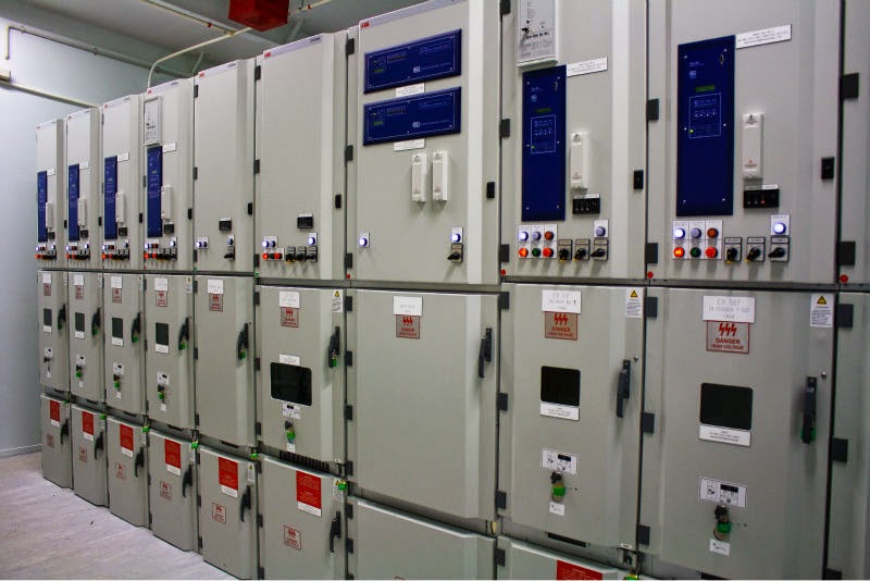
Advances in technology have increased the number of loads that can be driven by the units. Today, units are available with voltage and current ratings that can match the majority of three-phase induction motors found in buildings. With 500 horsepower units or higher available, facility executives have installed them on large capacity centrifugal chillers where very large energy savings can be achieved.
One of the most significant changes that has taken place recently is that with the widespread acceptance of the units and the recognition of the energy and maintenance benefits, manufacturers are including VFD controls as part of their system in a number of applications. For example, manufacturers of centrifugal chillers offer VFD controls as an option on a number of their units. Similarly, manufacturers of domestic water booster pump systems also offer the controls as part of their system, providing users with better control strategies while reducing energy and maintenance costs.

A Few Cautions

When evaluating the installation of a VFD, facility executives should take into consideration a number of factors related to the specifics of 
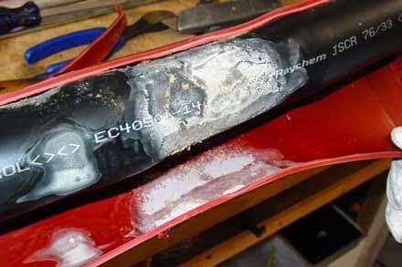
the application. For example, most VFDs emit a series of pulses that are rapidly switched. 

These pulses can be reflected back from the motor terminals into the cable that connects the VFD to the motor. 
In applications where there is a long run between the motor and the VFD, these reflected pulses can produce voltages that exceed the line voltage, causing stresses in the cable and motor windings that could lead to insulation failure. 
While this effect is not very significant in motors that operate at 230 volts or less, it is a concern for those that operate at 480 volts or higher. 

For those applications, minimize the distance between the VFD and the motor, use cabling specifically designed for use with VFDs, and consider installing a filter specifically designed to reduce the impact of the reflected pulses.
Another factor to consider is the impact the VFD may have on the motor's bearings. The pulses produced by the VFD can generate a voltage differential between the motor shaft and its casing. If this voltage is high enough, it can generate sparks in the bearings that erode their surfaces. 
 
This condition can also be avoided by using a cable designed specifically for use with VFDs.

Popular Posts

Text Widget

Engineerings Zone. Powered by Blogger.

Blockquote