Why we are use 11KV / 22KV / 33KV / 66KV / 110KV / 230KV / 440KV this type of ratio?

Why we are use 11KV / 22KV / 33KV / 66KV / 110KV / 230KV / 440KV this type of ratio. Why can’t we use other voltage ratio like 54KV / 99KV etc?

When an alternator generates voltage, we always use a multiple of 1.11 because for a pure sine wave the FORM FACTOR is the  ratio of rms value of voltage or current with the avg. value of voltage or current and for pure sine wave rms value of current is Imax/root '2' and avg. value is 2Imax/pie and which comes out to be 1.1;


We can't have a combination of other then a multiple of 1.11*.
So we can see all the voltages are made inevitably multiple of this value (1.1, which is the form factor of ac wave).

Also it provides us the best economic construction of step up and step down transformers.


* In the case of a Square Wave ie. a digital wave, the RMS and the average value are equal; therefore, the form factor is 1.


Different type of motors...

Different type of motors.....

Squirrel Cage Motor


Electric Motor

An Electric motor is a machine which converts electric energy into mechanical energy. Its action is based on the principle that when a current-carrying conductor is placed in a magnetic field, it experiences a mechanical force whose direction is given by Fleming’s Left-hand Rule and whose magnitude is given by F = BIl Newton.

Types of AC Motors

Classification Based On Principle of Operation:
(a) Synchronous Motors.
1. Plain
2. Super

(b) Asynchronous Motors.
1. Induction Motors:
(a) Squirrel Cage
(b) Slip-Ring (external resistance).
2. Commutator Motors:
(a) Series
(b) Compensated
(c) Shunt
(d) Repulsion
(e) Repulsion-start induction
(f) Repulsion induction
Classification Based On Type of Current:
1. Single Phase
2. Three Phase
Classification Based On Speed of Operation:
1. Constant Speed.
2. Variable Speed.
3. Adjustable Speed.
Classification Based On Structural Features:
1. Open
2. Enclosed
3. Semi-enclosed
4. Ventilated
5. Pipe-ventilated
6. Riveted frame-eye etc. 

Types of DC Motor

Most common DC motor types are-
1. Permanent-magnet motors
2. Brushed DC Motor
a.       DC shunt-wound motor
b.      DC series-wound motor
c.       DC compound motor
                                                              i.      Cumulative compound
                                                            ii.      Differentially compounded
d.      Permanent magnet DC motor
e.       Separately excited

3. Brushless DC Motor
4. Coreless or ironless DC motors
5. Printed armature or pancake DC motors
6. Universal motors


How to choose transformer rating?

 How to choose transformer rating?


When an installation is to be supplied directly from a MV/LV transformer and the maximum apparent-power loading of the installation has been determined, a suitable rating for the transformer can be decided, taking into account the following considerations:


  • The possibility of improving the power factor of the installation
  • Anticipated extensions to the installation
  • Installation constraints (e.g. temperature)
  • Standard transformer ratings.

3-phase transformer

The nominal full-load current In on the LV side of a 3-phase transformer is given by:

Formula - transformer rating

where:
  • Pa = kVA rating of the transformer
  • U = phase-to-phase voltage at no-load in volts (237 V or 410 V)
  • In is in amperes

Single-phase transformer

For a single-phase transformer:

Formula2 - transformer rating

where
  • V = voltage between LV terminals at no-load (in volts)
Simplified equation for 400 V (3-phase load)
  • In = kVA x 1.4
The IEC standard for power transformers is IEC 60076.

Degradation of Insulation in Switchgear (What’s Really Happening)

Partial Discharge

Partial Discharge (PD)

Electrical insulation is subjected to electrical and mechanical stress, elevated temperature and temperature variations, and environmental conditions especially for outdoor applications. In addition to normal operating conditions, there are a host of other factors that may trigger accelerated aging or deterioration of insulation.


Switching and lightning surges can start ionization in an already stressed area. Mechanical strikes during breaker operation can cause micro cracks and voids. Excessive moisture or chemical contamination of the surface can cause tracking. Any defects in design and manufacturing are also worth mentioning.
Partial Descharge


PD is a localized electrical discharge that does not completely bridge the electrodes. PD is a leading indicator of an insulation problem. Quickly accelerating PD activity can result in a complete insulation failure.

PD mechanism can be different depending on how and where the sparking occurs:
  • Voids and cavities are filled with air in poorly cast current transformers, voltage transformers and epoxy spacers. Since air has lower permittivity than insulation material, an enhanced electric field forces the voids to flash-over, causing PD. Energy dissipated during repetitive PD will carbonize and weaken the insulation.
  • Contaminants or moisture on the insulation induce the electrical tracking or surface PD. Continuous tracking will grow into a complete surface flash-over.
  • Corona discharge from sharp edge of a HV conductor is another type of PD. It produces ozone that aggressively attacks insulation and also facilitates flashover during periods of overvoltage.
Features of partial discharge activity, such as intensity, maximum magnitude, pulse rate, long-term trend, are important indications of the insulation’s condition.

Healthy switchgear has very little or no PD activity. If PD activity is significant, it will eventually deteriorate insulation to a complete failure. Higher voltages produce higher intensity partial discharges, thus PD detection in gear with higher voltages (13.8 kV and up) is more critical.

Possible locations of partial discharge in switchgear:
  1. Main bus insulation
  2. Circuit breaker insulation
  3. Current transformers
  4. Voltage transformers
  5. Cable terminations
  6. Support insulators
  7. Non-shielded cables in contact with other phases or ground


Electrical Switchgear Protection

Definition of Switchgear

A switchgear or electrical switchgear is a generic term which includes all the switching devices associated with mainly power system protection. It also includes all devices associated with control, metering and regulating of electrical power system. Assembly of such devices in a logical manner forms a switchgear. This is very basic definition of switchgear.

Switchgear and Protection

Switchgear
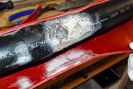
 We all familiar with low voltage switches and re-wirable fuses in our home. The switch is used to manually open and close the electrical circuit in our home and electrical fuse is used to protect our household electrical circuit from over  current  and short circuit faults. In same way every electrical circuit including high voltage electrical power system needs switching and protective devices. But in high voltage and extra high voltage system, these switching and protective scheme becomes complicated one for high fault  current  interruption in safe and secure way. In addition to that from commercial point of view every electrical power system needs measuring, control and regulating arrangement. Collectively the whole system is called switchgear and protection of power system. The electrical switchgear have been developing in various forms.

Switchgear protection plays a vital role in modern power system network, right from generation through transmission to distribution end. The  current  interruption device or switching device is called circuit breaker in switchgear protection system. The circuit breaker can be operated manually as when required and it is also operated during over  current  and short circuit or any other faults in the system by sensing the abnormality of system. The circuit breaker senses the faulty condition of system through protection relay and this relay is again actuated by faulty signal normally comes from current transformer or voltage transformer.

A switchgear has to perform the function of carrying, making and breaking the normal load current  like a switch and it has to perform the function of clearing the fault  in addition to that it also has provision of metering and regulating the various parameters of electrical power system. Thus the switchgear includes circuit breaker, current transformer, voltage transformer, protection relay, measuring instrument, electrical switch,electrical fuse, miniature circuit breaker, lightening arrestor or surge arrestor, electrical isolator and other associated equipment.
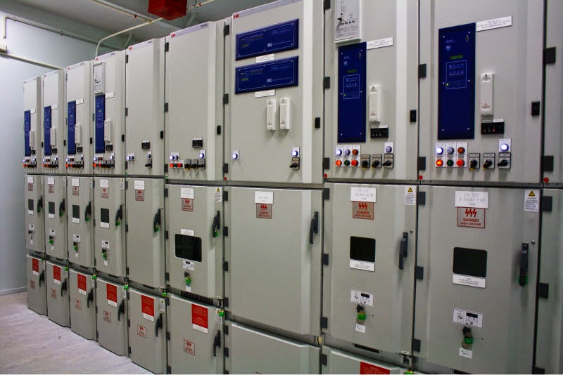
Switchgear Panels
 
 
Electric switchgear is necessary at every switching point in the electrical power system. There are various voltage levels and hence various fault levels between the generating stations and load centers. Therefore various types of switchgear assembly are required depending upon different voltage levels of the system.
 
Besides the power system network, electrical switchgear is  also required in industrial works, industrial projects, domestic and commercial buildings.


Popular Posts

Text Widget

Engineerings Zone. Powered by Blogger.

Blockquote